트랜스파일러 패스에서 DAG 사용하기
Qiskit에서는 트랜스파일 단계 내에서 Circuit이 DAG를 사용하여 표현됩니다. 일반적으로 DAG는 정점(노드라고도 함)과 정점 쌍을 특정 방향으로 연결하는 방향성 엣지로 구성됩니다. 이 표현은 개별 DagNode 객체로 구성된 qiskit.dagcircuit.DAGCircuit 객체를 사용하여 저장됩니다. 순수한 Gate 목록(즉, 넷리스트) 대비 이 표현의 장점은 연산 간 정보 흐름이 명시적으로 드러나 변환 결정을 내리기가 더 쉽다는 점입니다.
이 가이드에서는 DAG를 다루고 이를 활용하여 커스텀 Transpiler 패스를 작성하는 방법을 설명합니다. 먼저 간단한 Circuit을 구성하고 DAG 표현을 살펴본 후, 기본적인 DAG 연산을 탐색하고 커스텀 BasicMapper 패스를 구현합니다.
Circuit 구성 및 DAG 살펴보기
아래 코드 예시는 Bell 상태를 준비하고 측정 결과에 따라 회전을 적용하는 간단한 Circuit을 만들어 DAG를 설명합니다.
패키지 버전
이 페이지의 코드는 다음 요구 사항을 사용하여 개발되었습니다. 해당 버전 이상을 사용하길 권장합니다.
qiskit[all]~=2.4.0
# Added by doQumentation — required packages for this notebook
!pip install -q qiskit
from qiskit import QuantumRegister, ClassicalRegister, QuantumCircuit
from qiskit.converters import circuit_to_dag
from qiskit.visualization import circuit_drawer
from qiskit.visualization.dag_visualization import dag_drawer

# Create circuit
q = QuantumRegister(3, "q")
c = ClassicalRegister(3, "c")
circ = QuantumCircuit(q, c)
circ.h(q[0])
circ.cx(q[0], q[1])
circ.measure(q[0], c[0])

# Qiskit 2.0 uses if_test instead of c_if
with circ.if_test((c, 2)):
    circ.rz(0.5, q[1])

circuit_drawer(circ, output="mpl")

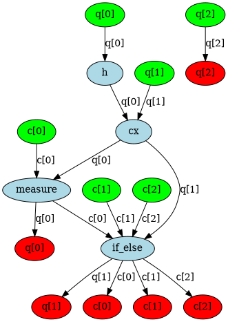
DAG에는 세 가지 종류의 그래프 노드가 있습니다: Qubit/clbit 입력 노드(녹색), 연산 노드(파란색), 출력 노드(빨간색). 각 엣지는 두 노드 간의 데이터 흐름(또는 의존성)을 나타냅니다. qiskit.tools.visualization.dag_drawer() 함수를 사용하여 이 Circuit의 DAG를 시각화할 수 있습니다. (이를 실행하려면 Graphviz 라이브러리를 설치하세요.)
# Convert to DAG
dag = circuit_to_dag(circ)
dag_drawer(dag)
기본 DAG 연산
아래 코드 예시는 노드 접근, 연산 추가, 서브 Circuit 대체 등 DAG와 관련된 일반적인 연산을 보여줍니다. 이러한 연산들은 Transpiler 패스를 구축하기 위한 기반이 됩니다.
DAG의 모든 연산 노드 가져오기
op_nodes() 메서드는 Circuit 내 DAGOpNode 객체의 이터러블 리스트를 반환합니다:
dag.op_nodes()
[DAGOpNode(op=Instruction(name='h', num_qubits=1, num_clbits=0, params=[]), qargs=(<Qubit register=(3, "q"), index=0>,), cargs=()),
 DAGOpNode(op=Instruction(name='cx', num_qubits=2, num_clbits=0, params=[]), qargs=(<Qubit register=(3, "q"), index=0>, <Qubit register=(3, "q"), index=1>), cargs=()),
 DAGOpNode(op=Instruction(name='measure', num_qubits=1, num_clbits=1, params=[]), qargs=(<Qubit register=(3, "q"), index=0>,), cargs=(<Clbit register=(3, "c"), index=0>,)),
 DAGOpNode(op=Instruction(name='if_else', num_qubits=1, num_clbits=3, params=[<qiskit.circuit.quantumcircuit.QuantumCircuit object at 0x7f1ca06de8d0>, None]), qargs=(<Qubit register=(3, "q"), index=1>,), cargs=(<Clbit register=(3, "c"), index=0>, <Clbit register=(3, "c"), index=1>, <Clbit register=(3, "c"), index=2>))]
각 노드는 DAGOpNode 클래스의 인스턴스입니다:
node = dag.op_nodes()[3]
print("node name:", node.name)
print("op:", node.op)
print("qargs:", node.qargs)
print("cargs:", node.cargs)
print("condition:", node.op.condition)
node name: if_else
op: Instruction(name='if_else', num_qubits=1, num_clbits=3, params=[<qiskit.circuit.quantumcircuit.QuantumCircuit object at 0x7f1c9ee9d650>, None])
qargs: (<Qubit register=(3, "q"), index=1>,)
cargs: (<Clbit register=(3, "c"), index=0>, <Clbit register=(3, "c"), index=1>, <Clbit register=(3, "c"), index=2>)
condition: (ClassicalRegister(3, 'c'), 2)
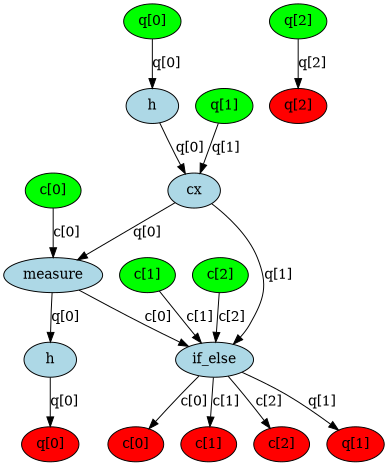
뒤에 연산 추가하기
apply_operation_back() 메서드를 사용하여 DAGCircuit의 끝에 연산을 추가합니다. 이렇게 하면 Circuit 내 기존 연산들 이후에 지정된 Gate가 해당 Qubit에 적용되도록 추가됩니다.
from qiskit.circuit.library import HGate

dag.apply_operation_back(HGate(), qargs=[q[0]])
dag_drawer(dag)
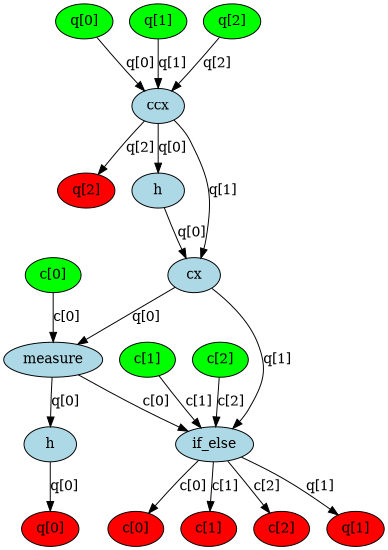
앞에 연산 추가하기
apply_operation_front() 메서드를 사용하여 DAGCircuit의 시작 부분에 연산을 추가합니다. 이렇게 하면 Circuit 내 기존 연산들보다 앞에 지정된 Gate가 삽입되어 실질적으로 첫 번째로 실행되는 연산이 됩니다.
from qiskit.circuit.library import CCXGate

dag.apply_operation_front(CCXGate(), qargs=[q[0], q[1], q[2]])
dag_drawer(dag)
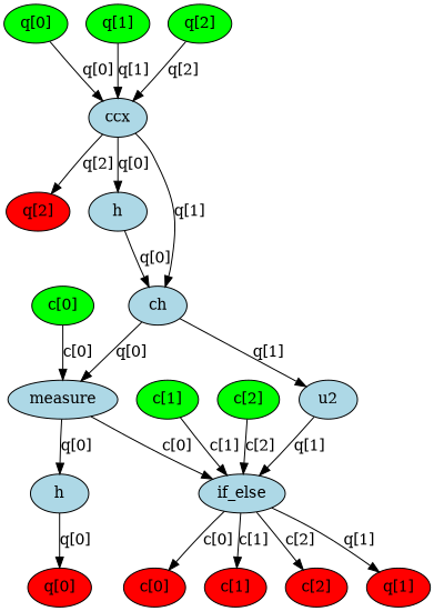
노드를 서브 Circuit으로 대체하기
DAGCircuit에서 특정 연산을 나타내는 노드를 서브 Circuit으로 교체합니다. 먼저 원하는 Gate 시퀀스로 새 서브 DAG를 구성한 다음, substitute_node_with_dag()를 사용하여 대상 노드를 이 서브 DAG로 대체하되 나머지 Circuit과의 연결은 유지합니다.
from qiskit.dagcircuit import DAGCircuit
from qiskit.circuit.library import CHGate, U2Gate, CXGate

# Build sub-DAG
mini_dag = DAGCircuit()
p = QuantumRegister(2, "p")
mini_dag.add_qreg(p)
mini_dag.apply_operation_back(CHGate(), qargs=[p[1], p[0]])
mini_dag.apply_operation_back(U2Gate(0.1, 0.2), qargs=[p[1]])

# Replace CX with mini_dag
cx_node = dag.op_nodes(op=CXGate).pop()
dag.substitute_node_with_dag(cx_node, mini_dag, wires=[p[0], p[1]])
dag_drawer(dag)
모든 변환이 완료된 후, DAG는 다시 일반적인 QuantumCircuit 객체로 변환될 수 있습니다. 이것이 Transpiler 파이프라인이 동작하는 방식입니다. Circuit을 가져와서 DAG 형태로 처리하고, 변환된 Circuit을 출력으로 만들어냅니다.
from qiskit.converters import dag_to_circuit

new_circ = dag_to_circuit(dag)
circuit_drawer(new_circ, output="mpl")

BasicMapper 패스 구현하기
DAG 구조는 Transpiler 패스를 작성하는 데 활용될 수 있습니다. 아래 예시에서는 임의의 Circuit을 제한된 qubit 연결성을 가진 장치에 매핑하기 위한 BasicMapper 패스를 구현합니다. 추가 안내는 커스텀 Transpiler 패스 작성 가이드를 참고하세요.
이 패스는 TransformationPass로 정의되며, Circuit을 수정합니다. DAG를 레이어 단위로 순회하면서 각 명령이 장치의 커플링 맵이 부과하는 제약 조건을 충족하는지 확인합니다. 위반이 감지되면 스왑 경로를 결정하고 필요한 SWAP Gate를 삽입합니다.
Transpiler 패스를 생성할 때 첫 번째 결정 사항은 패스가 TransformationPass를 상속할지 AnalysisPass를 상속할지 선택하는 것입니다. Transformation 패스는 Circuit을 수정하도록 설계된 반면, Analysis 패스는 이후 패스에서 사용할 정보를 추출하기 위한 용도입니다. 주요 기능은 run(dag) 메서드에 구현합니다. 마지막으로, 패스는 qiskit.transpiler.passes 모듈 내에 등록되어야 합니다.
이 특정 패스에서는 DAG를 레이어 단위로 순회합니다(각 레이어에는 서로 겹치지 않는 qubit 집합에 작용하는 연산들이 포함되어 독립적으로 실행될 수 있습니다). 각 연산에 대해 커플링 맵 제약 조건이 충족되지 않으면 적절한 스왑 경로를 찾아 관련 Qubit들을 인접하게 만드는 데 필요한 스왑을 삽입합니다.
from qiskit.transpiler.basepasses import TransformationPass
from qiskit.transpiler import Layout
from qiskit.circuit.library import SwapGate

class BasicSwap(TransformationPass):
    def __init__(self, coupling_map, initial_layout=None):
        super().__init__()
        self.coupling_map = coupling_map
        self.initial_layout = initial_layout

    def run(self, dag):
        new_dag = DAGCircuit()
        for qreg in dag.qregs.values():
            new_dag.add_qreg(qreg)
        for creg in dag.cregs.values():
            new_dag.add_creg(creg)

        if self.initial_layout is None:
            self.initial_layout = Layout.generate_trivial_layout(
                *dag.qregs.values()
            )

        current_layout = self.initial_layout.copy()

        for layer in dag.serial_layers():
            subdag = layer["graph"]
            for gate in subdag.two_qubit_ops():
                q0, q1 = gate.qargs
                p0 = current_layout[q0]
                p1 = current_layout[q1]

                if self.coupling_map.distance(p0, p1) != 1:
                    path = self.coupling_map.shortest_undirected_path(p0, p1)
                    for i in range(len(path) - 2):
                        wire1, wire2 = path[i], path[i + 1]
                        qubit1 = current_layout[wire1]
                        qubit2 = current_layout[wire2]
                        new_dag.apply_operation_back(
                            SwapGate(), qargs=[qubit1, qubit2]
                        )
                        current_layout.swap(wire1, wire2)

            new_dag.compose(
                subdag, qubits=current_layout.reorder_bits(new_dag.qubits)
            )

        return new_dag
이제 작은 예시 Circuit으로 패스를 테스트할 수 있습니다. 새로 정의한 패스를 포함한 패스 매니저를 구성합니다. 예시 Circuit을 이 패스 매니저에 제공하면 새로 변환된 Circuit이 출력으로 생성됩니다.
from qiskit.transpiler import CouplingMap, PassManager
from qiskit import QuantumRegister, QuantumCircuit

q = QuantumRegister(7, "q")
in_circ = QuantumCircuit(q)
in_circ.h(q[0])
in_circ.cx(q[0], q[4])
in_circ.cx(q[2], q[3])
in_circ.cx(q[6], q[1])
in_circ.cx(q[5], q[0])
in_circ.rz(0.1, q[2])
in_circ.cx(q[5], q[0])

coupling = [[0, 1], [1, 2], [2, 3], [3, 4], [4, 5], [5, 6]]
coupling_map = CouplingMap(couplinglist=coupling)

pm = PassManager()
pm.append(BasicSwap(coupling_map))

out_circ = pm.run(in_circ)

in_circ.draw(output="mpl")
out_circ.draw(output="mpl")

다음 단계
- 커스텀 Transpiler 패스 생성에 관한 가이드를 검토하세요.
- 커스텀 Backend 생성 및 트랜스파일 방법을 알아보세요.
- Transpiler 설정 비교 가이드를 시도해 보세요.
- DAG Circuit API 문서를 검토하세요.