커스텀 Backend 생성 및 트랜스파일
# Added by doQumentation — required packages for this notebook
!pip install -q numpy qiskit rustworkx
# Don't use SVGs for this file because the images are too large,
# and the SVGs are much larger than their PNGs equivalents.
%config InlineBackend.figure_format='png'
```json

{/* cspell:ignore multichip interchip Lasciate ogne speranza voi ch'intrate */}
{/*
  DO NOT EDIT THIS CELL!!!
  This cell's content is generated automatically by a script. Anything you add
  here will be removed next time the notebook is run. To add new content, create
  a new cell before or after this one.
*/}

<details>
<summary><b>패키지 버전</b></summary>

이 페이지의 코드는 아래 요구 사항을 사용하여 개발되었습니다.
해당 버전 이상을 사용하는 것을 권장합니다.
qiskit[all]~=2.4.0
</details>
{/* cspell:ignore LOCC */}

Qiskit의 강력한 기능 중 하나는 고유한 디바이스 구성을 지원하는 능력입니다. Qiskit은 사용하는 양자 하드웨어의 공급자에 구애받지 않도록 설계되어 있으며, 공급자는 자신만의 고유한 디바이스 속성에 맞게 `BackendV2` 객체를 구성할 수 있습니다. 이 주제에서는 나만의 Backend를 구성하고 양자 Circuit을 해당 Backend에 맞게 트랜스파일하는 방법을 설명합니다.

다양한 기하학적 구조나 기저 Gate를 가진 고유한 `BackendV2` 객체를 생성하고, 해당 구성을 고려하여 Circuit을 트랜스파일할 수 있습니다. 아래 예제는 분리된 qubit 격자를 가진 Backend를 다루며, 이 Backend의 기저 Gate는 내부 벌크와 엣지가 서로 다릅니다.

## Provider, BackendV2, Target 인터페이스 이해하기 \{#understand-the-provider-backendv2-and-target-interfaces}

시작하기 전에 [`Provider`](../api/qiskit/providers), [`BackendV2`](../api/qiskit/qiskit.providers.BackendV2), [`Target`](../api/qiskit/qiskit.transpiler.Target) 객체의 사용 방법과 목적을 이해하는 것이 도움이 됩니다.

- 양자 디바이스나 시뮬레이터를 Qiskit SDK에 통합하려면 자신만의 `Provider` 클래스를 작성해야 합니다. 이 클래스는 단 하나의 목적을 수행합니다: 제공하는 Backend 객체를 가져오는 것입니다. 여기서 필요한 자격 증명 및/또는 인증 작업이 처리됩니다. 인스턴스화되면 provider 객체는 Backend 목록과 함께 Backend를 획득/인스턴스화하는 기능을 제공합니다.

- 다음으로, Backend 클래스는 Qiskit SDK와 Circuit을 실행할 하드웨어 또는 시뮬레이터 사이의 인터페이스를 제공합니다. Backend를 Transpiler에 설명하는 데 필요한 모든 정보를 포함하여, 제약 조건에 따라 Circuit을 최적화할 수 있도록 합니다. `BackendV2`는 네 가지 주요 부분으로 구성됩니다:
  - Backend의 제약 조건에 대한 설명을 포함하고 Transpiler를 위한 Backend 모델을 제공하는 [`Target`](../api/qiskit/qiskit.transpiler.Target) 속성
  - Backend가 단일 작업에서 실행할 수 있는 Circuit 수의 한도를 정의하는 `max_circuits` 속성
  - 작업 제출을 수락하는 `run()` 메서드
  - 사용자 구성 가능한 옵션과 기본값을 정의하는 `_default_options` 집합

## 커스텀 BackendV2 생성하기 \{#create-a-custom-backendv2}

`BackendV2` 객체는 공급자가 생성하는 모든 Backend 객체에 사용되는 추상 클래스입니다(`qiskit.providers` 내부 또는 [`qiskit_ibm_runtime.IBMBackend`](../api/qiskit-ibm-runtime/ibm-backend)와 같은 다른 라이브러리). 위에서 언급한 바와 같이, 이 객체들은 [`Target`](https://docs.quantum.ibm.com/api/qiskit/qiskit.transpiler.Target)을 포함한 여러 속성을 포함합니다. `Target`은 [`Coupling Map`](https://docs.quantum.ibm.com/api/qiskit/qiskit.transpiler.CouplingMap), [`Instructions`](https://docs.quantum.ibm.com/api/qiskit/qiskit.circuit.Instruction) 목록 등 Backend의 속성을 Transpiler에 지정하는 정보를 포함합니다. `Target` 외에도 [`DriveChannel`](https://docs.quantum.ibm.com/api/qiskit/1.4/qiskit.pulse.channels.DriveChannel)이나 [`ControlChannel`](https://docs.quantum.ibm.com/api/qiskit/1.4/qiskit.pulse.channels.ControlChannel)과 같은 펄스 수준의 세부 정보도 정의할 수 있습니다.

다음 예제는 각 칩이 heavy-hex 연결성을 가지는 시뮬레이션된 멀티칩 Backend를 생성하여 이 커스터마이징을 시연합니다. 이 예제에서는 각 칩 내부에는 [`CZGates`](../api/qiskit/qiskit.circuit.library.CZGate)를, 칩 간에는 [`CXGates`](../api/qiskit/qiskit.circuit.library.ECRGate)를 2-Qubit Gate 집합으로 지정합니다. 먼저 자신만의 `BackendV2`를 생성하고, 앞서 설명한 제약 조건에 따라 단일 및 2-Qubit Gate로 `Target`을 커스터마이징합니다.

<Admonition type="tip" title="graphviz 라이브러리">
Coupling Map을 시각화하려면 [`graphviz`](https://graphviz.org/) 라이브러리가 설치되어 있어야 합니다.
</Admonition>

```python
import numpy as np
import rustworkx as rx

from qiskit.providers import BackendV2, Options
from qiskit.transpiler import Target, InstructionProperties
from qiskit.circuit.library import XGate, SXGate, RZGate, CZGate, ECRGate
from qiskit.circuit import Measure, Delay, Parameter, Reset
from qiskit import QuantumCircuit, transpile
from qiskit.visualization import plot_gate_map

class FakeLOCCBackend(BackendV2):
    """Fake multi chip backend."""

    def __init__(self, distance=3, number_of_chips=3):
        """Instantiate a new fake multi chip backend.

        Args:
            distance (int): The heavy hex code distance to use for each chips'
                coupling map. This number **must** be odd. The distance relates
                to the number of qubits by:
                :math:`n = \\frac{5d^2 - 2d - 1}{2}` where :math:`n` is the
                number of qubits and :math:`d` is the ``distance``
            number_of_chips (int): The number of chips to have in the multichip backend
                each chip will be a heavy hex graph of ``distance`` code distance.
        """
        super().__init__(name="Fake LOCC backend")
        # Create a heavy-hex graph using the
        # rustworkx library, then instantiate a new target
        self._graph = rx.generators.directed_heavy_hex_graph(
            distance, bidirectional=False
        )
        num_qubits = len(self._graph) * number_of_chips
        self._target = Target(
            "Fake multi-chip backend", num_qubits=num_qubits
        )

        # Generate instruction properties for single qubit gates and a measurement, delay,
        #  and reset operation to every qubit in the backend.
        rng = np.random.default_rng(seed=12345678942)
        rz_props = {}
        x_props = {}
        sx_props = {}
        measure_props = {}
        delay_props = {}

        # Add 1q gates. Globally use virtual rz, x, sx, and measure
        for i in range(num_qubits):
            qarg = (i,)
            rz_props[qarg] = InstructionProperties(error=0.0, duration=0.0)
            x_props[qarg] = InstructionProperties(
                error=rng.uniform(1e-6, 1e-4),
                duration=rng.uniform(1e-8, 9e-7),
            )
            sx_props[qarg] = InstructionProperties(
                error=rng.uniform(1e-6, 1e-4),
                duration=rng.uniform(1e-8, 9e-7),
            )
            measure_props[qarg] = InstructionProperties(
                error=rng.uniform(1e-3, 1e-1),
                duration=rng.uniform(1e-8, 9e-7),
            )
            delay_props[qarg] = None
        self._target.add_instruction(XGate(), x_props)
        self._target.add_instruction(SXGate(), sx_props)
        self._target.add_instruction(RZGate(Parameter("theta")), rz_props)
        self._target.add_instruction(Measure(), measure_props)
        self._target.add_instruction(Reset(), measure_props)

        self._target.add_instruction(Delay(Parameter("t")), delay_props)
        # Add chip local 2q gate which is CZ
        cz_props = {}
        for i in range(number_of_chips):
            for root_edge in self._graph.edge_list():
                offset = i * len(self._graph)
                edge = (root_edge[0] + offset, root_edge[1] + offset)
                cz_props[edge] = InstructionProperties(
                    error=rng.uniform(7e-4, 5e-3),
                    duration=rng.uniform(1e-8, 9e-7),
                )
        self._target.add_instruction(CZGate(), cz_props)

        cx_props = {}
        # Add interchip 2q gates which are ecr (effectively CX)
        # First determine which nodes to connect
        node_indices = self._graph.node_indices()
        edge_list = self._graph.edge_list()
        inter_chip_nodes = {}
        for node in node_indices:
            count = 0
            for edge in edge_list:
                if node == edge[0]:
                    count += 1
            if count == 1:
                inter_chip_nodes[node] = count
        # Create inter-chip ecr props
        cx_props = {}
        inter_chip_edges = list(inter_chip_nodes.keys())
        for i in range(1, number_of_chips):
            offset = i * len(self._graph)
            edge = (
                inter_chip_edges[1] + (len(self._graph) * (i - 1)),
                inter_chip_edges[0] + offset,
            )
            cx_props[edge] = InstructionProperties(
                error=rng.uniform(7e-4, 5e-3),
                duration=rng.uniform(1e-8, 9e-7),
            )

        self._target.add_instruction(ECRGate(), cx_props)

    @property
    def target(self):
        return self._target

    @property
    def max_circuits(self):
        return None

    @property
    def graph(self):
        return self._graph

    @classmethod
    def _default_options(cls):
        return Options(shots=1024)

    def run(self, circuit, **kwargs):
        raise NotImplementedError(
            "This backend does not contain a run method"
        )
Backend 시각화하기
qiskit.visualization 모듈의 plot_gate_map() 메서드를 사용하면 이 새로운 클래스의 연결 그래프를 볼 수 있습니다. 이 메서드는 plot_coupling_map() 및 plot_circuit_layout()과 함께 Backend의 qubit 배치와 Backend의 qubit 전반에 걸친 Circuit 레이아웃을 시각화하는 데 유용한 도구입니다. 이 예제는 세 개의 작은 heavy-hex 칩을 포함하는 Backend를 생성합니다. Qubit을 배치하기 위한 좌표 집합과 서로 다른 2-Qubit Gate에 대한 커스텀 색상 집합을 지정합니다.
backend = FakeLOCCBackend(3, 3)

target = backend.target
coupling_map_backend = target.build_coupling_map()

coordinates = [
    (3, 1),
    (3, -1),
    (2, -2),
    (1, 1),
    (0, 0),
    (-1, -1),
    (-2, 2),
    (-3, 1),
    (-3, -1),
    (2, 1),
    (1, -1),
    (-1, 1),
    (-2, -1),
    (3, 0),
    (2, -1),
    (0, 1),
    (0, -1),
    (-2, 1),
    (-3, 0),
]

single_qubit_coordinates = []
total_qubit_coordinates = []

for coordinate in coordinates:
    total_qubit_coordinates.append(coordinate)

for coordinate in coordinates:
    total_qubit_coordinates.append(
        (-1 * coordinate[0] + 1, coordinate[1] + 4)
    )

for coordinate in coordinates:
    total_qubit_coordinates.append((coordinate[0], coordinate[1] + 8))

line_colors = ["#adaaab" for edge in coupling_map_backend.get_edges()]
ecr_edges = []

# Get tuples for the edges which have an ecr instruction attached
for instruction in target.instructions:
    if instruction[0].name == "ecr":
        ecr_edges.append(instruction[1])

for i, edge in enumerate(coupling_map_backend.get_edges()):
    if edge in ecr_edges:
        line_colors[i] = "#000000"
print(backend.name)
plot_gate_map(
    backend,
    plot_directed=True,
    qubit_coordinates=total_qubit_coordinates,
    line_color=line_colors,
)
Fake LOCC backend
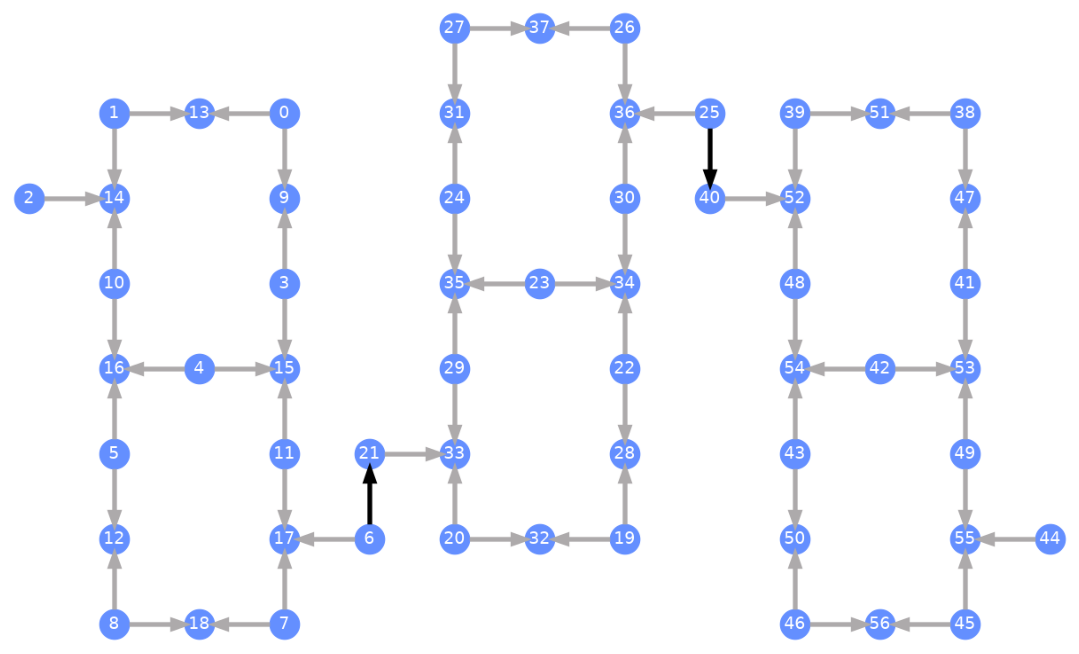
각 Qubit은 레이블이 붙어 있으며, 색상이 있는 화살표는 2-Qubit Gate를 나타냅니다. 회색 화살표는 CZ Gate이고, 검은 화살표는 칩 간 CX Gate입니다(qubit 과 을 연결합니다). 화살표의 방향은 이 Gate들이 실행되는 기본 방향을 나타내며, 각 2-Qubit 채널에서 기본적으로 어느 Qubit이 제어/타깃인지를 지정합니다.
커스텀 Backend에 대해 Transpile하기
고유한 Target을 가진 커스텀 Backend가 정의되었으므로, 이 Backend에 대해 양자 Circuit을 Transpile하는 것은 간단합니다. Transpiler 패스에 필요한 모든 관련 제약 조건(기저 Gate, qubit 연결성 등)이 이 속성 안에 포함되어 있기 때문입니다. 다음 예제는 대규모 GHZ 상태를 생성하는 Circuit을 구성하고, 위에서 만든 Backend에 대해 Transpile합니다.
from qiskit.transpiler import generate_preset_pass_manager

num_qubits = 50
ghz = QuantumCircuit(num_qubits)
ghz.h(range(num_qubits))
ghz.cx(0, range(1, num_qubits))
op_counts = ghz.count_ops()

print("Pre-Transpilation: ")
print(f"CX gates: {op_counts['cx']}")
print(f"H gates: {op_counts['h']}")
print("\n", 30 * "#", "\n")

pm = generate_preset_pass_manager(optimization_level=3, backend=backend)
transpiled_ghz = pm.run(ghz)
op_counts = transpiled_ghz.count_ops()

print("Post-Transpilation: ")
print(f"CZ gates: {op_counts['cz']}")
print(f"ECR gates: {op_counts['ecr']}")
print(f"SX gates: {op_counts['sx']}")
print(f"RZ gates: {op_counts['rz']}")
Pre-Transpilation:
CX gates: 49
H gates: 50

 ##############################
Post-Transpilation:
CZ gates: 146
ECR gates: 6
SX gates: 302
RZ gates: 250
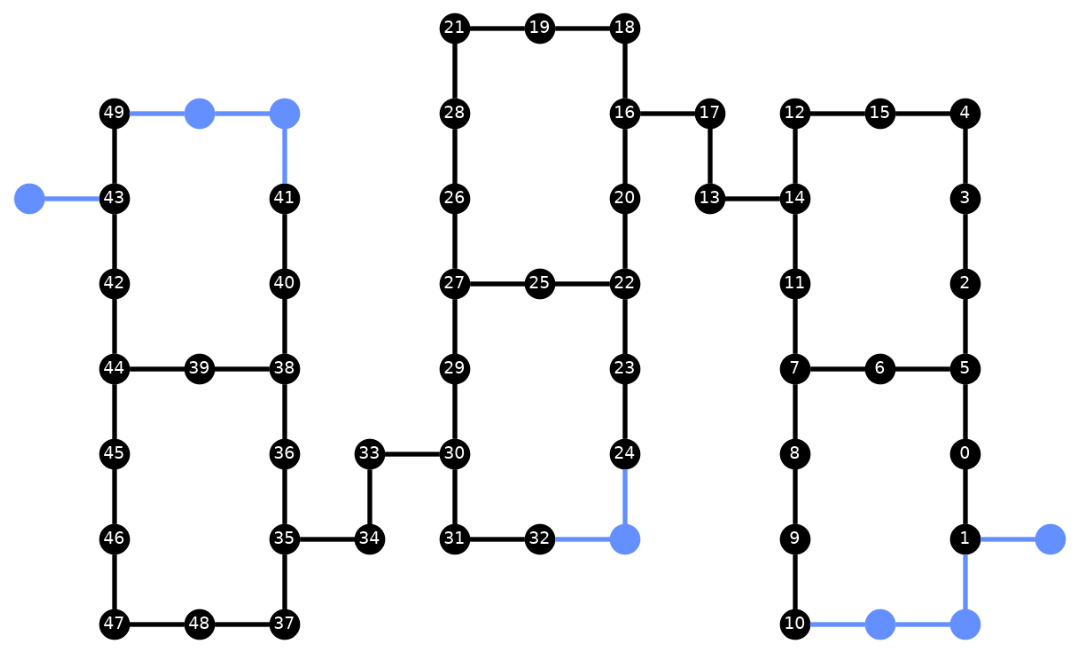
Transpile된 Circuit에는 이제 CZ와 ECR Gate가 혼합되어 있습니다. 이는 Backend의 Target에서 기저 Gate로 지정한 것들입니다. 또한 레이아웃 선택 후 SWAP 명령을 삽입해야 하기 때문에, 처음보다 훨씬 많은 Gate가 포함되어 있습니다. 아래에서는 plot_circuit_layout() 시각화 도구를 사용하여 이 Circuit에서 어떤 Qubit과 2-Qubit 채널이 사용되었는지 확인합니다.
from qiskit.visualization import plot_circuit_layout

plot_circuit_layout(
    transpiled_ghz, backend, qubit_coordinates=total_qubit_coordinates
)
고유한 Backend 만들기
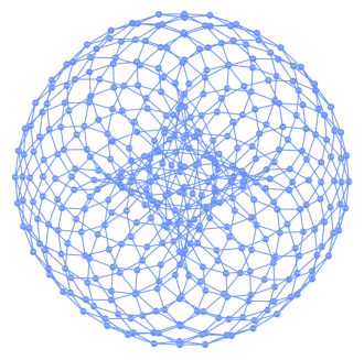
rustworkx 패키지에는 다양한 그래프 라이브러리가 포함되어 있으며, 커스텀 그래프를 생성할 수 있습니다. 아래의 시각적으로 흥미로운 코드는 토릭 코드(toric code)에서 영감을 받은 Backend를 생성합니다. 그런 다음 Backend 시각화 섹션의 함수를 사용하여 Backend를 시각화할 수 있습니다.
class FakeTorusBackend(BackendV2):
    """Fake multi chip backend."""

    def __init__(self):
        """Instantiate a new backend that is inspired by a toric code"""
        super().__init__(name="Fake LOCC backend")
        graph = rx.generators.directed_grid_graph(20, 20)
        for column in range(20):
            graph.add_edge(column, 19 * 20 + column, None)
        for row in range(20):
            graph.add_edge(row * 20, row * 20 + 19, None)
        num_qubits = len(graph)
        rng = np.random.default_rng(seed=12345678942)
        rz_props = {}
        x_props = {}
        sx_props = {}
        measure_props = {}
        delay_props = {}
        self._target = Target("Fake Kookaburra", num_qubits=num_qubits)
        # Add 1q gates. Globally use virtual rz, x, sx, and measure
        for i in range(num_qubits):
            qarg = (i,)
            rz_props[qarg] = InstructionProperties(error=0.0, duration=0.0)
            x_props[qarg] = InstructionProperties(
                error=rng.uniform(1e-6, 1e-4),
                duration=rng.uniform(1e-8, 9e-7),
            )
            sx_props[qarg] = InstructionProperties(
                error=rng.uniform(1e-6, 1e-4),
                duration=rng.uniform(1e-8, 9e-7),
            )
            measure_props[qarg] = InstructionProperties(
                error=rng.uniform(1e-3, 1e-1),
                duration=rng.uniform(1e-8, 9e-7),
            )
            delay_props[qarg] = None
        self._target.add_instruction(XGate(), x_props)
        self._target.add_instruction(SXGate(), sx_props)
        self._target.add_instruction(RZGate(Parameter("theta")), rz_props)
        self._target.add_instruction(Measure(), measure_props)
        self._target.add_instruction(Reset(), measure_props)
        self._target.add_instruction(Delay(Parameter("t")), delay_props)
        cz_props = {}
        for edge in graph.edge_list():
            cz_props[edge] = InstructionProperties(
                error=rng.uniform(7e-4, 5e-3),
                duration=rng.uniform(1e-8, 9e-7),
            )
        self._target.add_instruction(CZGate(), cz_props)

    @property
    def target(self):
        return self._target

    @property
    def max_circuits(self):
        return None

    @classmethod
    def _default_options(cls):
        return Options(shots=1024)

    def run(self, circuit, **kwargs):
        raise NotImplementedError("Lasciate ogne speranza, voi ch'intrate")
backend = FakeTorusBackend()
# We set `figsize` to a smaller size to make the documentation website faster
# to load. Normally, you do not need to set the argument.
plot_gate_map(backend, figsize=(4, 4))
num_qubits = int(backend.num_qubits / 2)
full_device_bv = QuantumCircuit(num_qubits, num_qubits - 1)
full_device_bv.x(num_qubits - 1)
full_device_bv.h(range(num_qubits))
full_device_bv.cx(range(num_qubits - 1), num_qubits - 1)
full_device_bv.h(range(num_qubits))
full_device_bv.measure(range(num_qubits - 1), range(num_qubits - 1))
tqc = transpile(full_device_bv, backend, optimization_level=3)
op_counts = tqc.count_ops()
print(f"CZ gates: {op_counts['cz']}")
print(f"X gates: {op_counts['x']}")
print(f"SX gates: {op_counts['sx']}")
print(f"RZ gates: {op_counts['rz']}")
CZ gates: 834
X gates: 18
SX gates: 1534
RZ gates: 1150